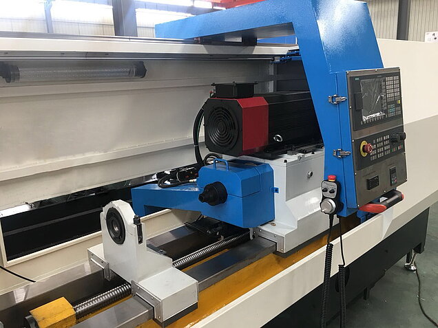
BTA Deep Hole Drilling Machine
Profimach PDHB-Series
PDHB-100-Series: deephole drilling machine (max counter boring hole diameter is 100mm).
PDHB-200-Series: deep hole drilling machine (max counter boring hole diameter is 200mm).
PDHB-250-Series: deep hole drilling and boring machine (max counter boring hole diameter is 250mm).
PDHB-350-Series: BTA deep hole drilling machine (max counter boring hole diameter is 350mm).
PDHB-500-Series: BTA deep hole drilling and boring machine (max counter boring hole diameter is 500mm).
PDHB-800-Series: deephole bore machine (max counter boring hole diameter is 800mm).
Diameter
- Solid drilling 20mm to 150mm,
- Counter boring from 30mm to 500mm
- Trepanning till 800 mm
Length
- Can drill/bore the depth up to 15.000mm. (depends on different models).
- Length to diameter ratio reachable 400:1 (depends tooling and material)
Deep drilling deviation:
- If both tools and job rotate,the deviation is 0.5mm per 1000mm,
- If only gun drill or job rotate,the deviation is 1mm per 1000mm.
Hole finished roughness:
- Solid drilling: IT9-IT11. hole roughness: Ra3.2um-Ra6.3um.
- Rough boring: T8-IT9. hole roughness: Ra3.2um-Ra6.3um.
- Fine boring: IT7-IT9. hole roughness: Ra1.6um-Ra3.2um.
- Burnishing: IT6-IT7. hole roughness: Ra0.2um-Ra0.4um.
Drilling different holes:
through hole,
blind hole,
concentric hole,
eccentric hole,
step hole.
Automation:automatic loading and unloading feeding system is optional.
CNC controller: Siemens/Fanuc/GSK CNC /PLC controller.
- Cart
- Air conditioner for electrical box
- Coolant pump
- Steady rest for tools
- Working light
- Tool box
- English operation manual.
CNC controller: Siemens/Fanuc/GSK CNC /PLC controller.
- Auto chips conveyor
- Drum type paper filter
- Guide bush
- Steady rest guide bush
- Oil centrifugal extractor
- Transformer
- Coolant chiller
- Full cover safety guard.
Automation: automatic loading and unloading feeding system is optional.
- Molds industry:water hole of molds,Thimble hole, runner hole, guide post hole and bottle mold hole.
- Hydraulic industry: hydraulic cylinder,servo hydraulic cylinder,industry cylinder,piston,oil hole of hydraulic valve block.
- Automobile industry: cylinder head, cylinder block (internal combustion engine), crankshaft, steering gear rack, gear shaft and valve core.
- Roll industry: Metallurgical roll, corrugated rod of paper industry.
- Oil pump nozzle industry: injection gas, needle valve body, plunger sleeve and other parts.
- Textile machinery industry: all kinds of spindle center hole, eccentric hole processing, etc.
- Medical equipment industry: titanium alloy, stainless steel 316 (titanium alloy) bone needle and other shaft .
- Military industry: test torpedo launch tube, antimissile launch tube, high-speed oil cylinder, reentry machine parts, etc.
- Coal industry: hydraulic cylinder products, etc.

Deep hole drilling and boring machine
Deep hole drilling and boring machines produced for Profimach are adopting internal chip-discharging strategy (BTA), which handles diameter from Φ30mm to Φ100mm (drilling), our deep hole machine's drilling, boring and rolling functions are applicable to propeller, landing gear and ejection seat; various barrels in military use; Our deep hole drilling and boring machine's boring diameter ranges from Ф40mm to Ф800mm, with maximum length of 16m.

MACHINE BED
The bed consists of high resistance and stiff rectangular sections, appropriately ribbed with two flat guide ways that are opportunely sized for maximum rigidity. To ensure that the optimum rigidity and stiffness in the machine bed is guaranteed, the latest CAE techniques are used to determine the optimum design of the bed structure. Supplementary the machine bed is optimized by using advanced FEA software for thermal stability, vibration resistance and improved accuracy. Oversized dimensioned, heavily ribbed structure which is fixed to the floor over its entire length with different support and leveling points, allowing a rigid fixing to the foundation.
PRECISION GROUND HARDENED SLIDEWAYS
Box slide ways are rigidly fixed into the machine bed structure for high rigidity and strength. By using a slide way design, the moving parts slide against each other, assisted by a layer of lubrication oil, which when applied correctly produces a hydrodynamic bearing. That is it is a bearing that glides on a controlled layer of lubrication created by motion. The guide ways are induction hardened and completely grinded for the entire length and have a hardness of 52-55 HRC.
The main features profimach's hardened box slide ways are as follows:
- Low friction surface due to the evenly dispersed oil film and antifriction material
- Machined and surface hardened to HRC 55, using ultra-high frequency heating, followed by rapid quenching and annealing.
- Following heat treatment, the slide ways are ground to ensure finishing accuracy.
- This produces an extremely hard, yet tough structure to ensure a long service life.
- Depth of hardness is over 5mm
- Box slide ways have a high dynamic stiffness because of their high static stiffness and high damping capacity.
The carriageways have all been hand scraped, which is a highly skilled trade to properly fit the carriages to the way surfaces. This hand scraping ensures that the machines are both geometrically correct and long lasting. The scraping procedure attempts to spread the points of bearing contact evenly across the whole bearing face and to achieve correct geometric alignments.
BORING CARRIAGE
Stress released high quality Cast iron made, the infinity variable feeds are granted through A.C. Brushless motors controlled by its electronic digital drives. The transmission is obtained with pinions engaged on a helical-toothed rack fixed in the center of the bed, with a special drive that permits the compensation of the thrust forces and moves backlash-free or by an oversized high precision Balscrew with high torque motor.
Carriage guides have antifriction material (TURCITE) for a precise and accurate movement to avoid any stick-slip problems even at low feed speeds. Taper gibs provides precise adjusting of carriage geometry. The guides lubrication of the carriage is automatic and centralized lubrication control provides trough autonomous electropump and tank. There is an electric oil level signal to control whenever there is a lost of oil and gives directly the message to the CNC.
In order to optimize any resistance the drive is duly dimensioned with big torque and low inertia, in order to achieve high acceleration. Scrapers grant the fine and good cleaning of the guideways’ surface.
To control and save the pieces and tools there is a carriage movement overload protection that is electronically made directly on the digital motor drive, that,during machining when the tool force comes to limit is working as follows :
- Feed stop of boring carriage
- Automatic backward motion of boring head from about mm. 20 (opt)
- Spindle stop
- Pumping station stop
ROTATING BORING HEAD/SPINDLE
Headstock
The head, casting made, mounted on the boring carriage, is of a box double walled structure, appropriately dimensioned with suitable ribs. It offers maximum rigidity and ensures chatter free operations, also during the most severe working conditions.
Some of the main features of our machine spindle/boring head are as follows:
- The well ribbed headstock ensures maximum heat dissipation.
- Thick cast iron casing absorbs cutting vibrations
- Large angular thrust bearings for heavy duty boring operations
- Roller bearings with large bearing areas for increased spindle rigidity.
- P4 class front roller bearing ensures smooth even turning and has high radial load capabilities.
- To increase spindle stiffness and ensure longer spindle life the spindle shaft is surface hardened at the bearing contact points before the final grinding process. This provides a tough inner core to absorb the cutting forces while the hardened areas at the loading points prevent rapid wear on the spindleshaft, thus producing a long lived spindle.
- The latest computer analysis techniques are used for bearing arrangement on the spindle shaft to ensure optimum stability in the spindle structure.
- Thick Meehanite cast housing absorbs and dampens cutting vibrations.
- Well ribbed housing quickly dissipates heat from bearings and improves cutting accuracy.
- To optimise headstock design, computer simulations and dynamic analysis are performed to better understand the stress applied to the headstock during heavy cutting.
- After headstock assembly, each spindle undergoes running tests for 8 - 24 hours to ensure bearing temperature is not excessive.
The speed-change gear box can be manual or hydraulically/servo controlled, and the shifting is confirmed by means of light indicators. The speed-change can be directly carried out through functions "M" or, in case the machine is manually operated, by the appropriate switch on the control panel.
By the control unit, the spindle speed values are directly programmed in R.P.M. The lubrication of all power transmission parts is ensured by a forced circulation unit, which supplies the oil mist to all mechanism in movement and is controlled by a flowswitch.

Toolbar/drilling tube
Drill tube systems connect precision cutting tools to the powerful motor of the machine. Strength, straightness, and durability of these components contribute to accurate drilling.
Drill Tubes
Drill tubes connect the drill head to the machine spindle, and use a standard size system for consistency around the globe. A precision hole starts with high quality drill tubes and solid connections.
Drill Tube Driver System and Clamp Reducers
The driver system connects the machine spindle to the drill tube and transmits power. Reducers allow multiple sizes of drill tubes per clamp range. These components are made of heat treated alloy for strength, durability, and accuracy. Connecting chucks are manufactured to customers request and designed to a specific STS/BTA drill tube. Chucks are available in a variety of spindle nose styles and sizes. Suitable for rotating as well as stationary tools. Bushes must be manufactured to suit each drill tube diameter used.
Drill Tube Adapters
Adapters are precision machined to securly attach SRB heads to a smaller range of drill tubes, reducing tooling package costs without sacrificing performance.

Vibration Dampeners
Vibration dampeners allow rotating drill tubes to be guided while dampening vibrations, resulting in a better finish and predictable tool life.
Vibration Dampener Carriage
A vibration dampener carriage is mounted onto the tracks of the machine and securely hold components to dampen vibrations in the drill tube. These are engineered for strength and manufactured out of cast iron. The number of dampeners required is based on an engineering analysis of hole depth.
Vibration Dampener Cartridges
Vibrations not only affect the surface finish and shorten tool life, but also force changes in cutting data which result in production loss. In order to control these vibrations better, we use a line of high end vibration dampers. These dampers are clamped externally to the drilltube and act as supports for the drill.
The damper assembly is mounted in a steady-rest(s), supplied with the machine ( 3 pieces for 6m machine). The damping pressure can be adjusted. Phenolic bushes for full contact are manufactured for each drill tube size and are slotted and tapered for maximum damping.
Cartridges fit perfectly within the dampener carriage and hold various sizes of collets, allowing smooth rotation on precision bearings. Cartridges come in standard sizes to reduce costs while allowing maximum drilling ranges.
Vibration Dampener Collets (optional)
Collets are made from a special dampening material that does not damage drill tube surface. These are mounted in vibration dampener cartridges and fit snugly around each size of drill tube.
Pressure Head System
Pressure head systems are where the tooling meets the workpiece, the coolant is introduced, and the drilling process begins.
PRESSURE HEAD
Pressure heads locate and clamp the work piece, guide the tooling head and introduce cutting fluid to the operation. The pressure head is critical for accurate skiving and roller burnishing drilling. Good and secure enclosure of oil pressure head to the workpiece . At the top part of support there are boring hole for placing of oil pressure heads of different dimensions. Connection to the coolant/oil feeding system made thourhg rapid connetctions .
Packing Glands
Packing glands provide a fluid seal for the drill tube as it enters the pressure head. These assemblies also guide the drill tube for straight and accurate drilling.
Bushing System
A master bushing system enables a range of drill sizes to fit, using cost-effective perishable bushings. These mount securely to the pressure head chuck.
TUBE clamping system
Workholding components and workpiece supports hold workpieces at either end, as well as in the middle, and make it easy to handle extremely heavy parts to maximize the skiving roller burnishing process

CLAMPING WORKHEAD + LANTERN
We have two models possible with fixed workhead or with moveble/clamping workhead. When moveble :Rapid feed and movement are made through hydraulic type motor or electrical servo motor controlled by its digital servovalve. The transmission is obtained with an oversized high precision double nut ballscrew, powered by an high torque hydraulic motor controlled by servo valve
The lantern is collecting all chips and oil after machining and bring it to the cleaning and pumping station
WORKREST
The workrest provides additional support of the workpiece during setup.This reduce the setup time and changeovertime drastically. Manual adjustable to fit in size and model of cutting Tools.
FORCED LUBRICATION
central automatic lubrication system
All slideways and moving members are automatically lubricated. Lubrication channels are milled into the underside of the carriageway and turret to allow oil to be constantly forced between the moving members for added machine life.
The lubricant is controlled through pressured system that monitors the amount of oil in circulation. Any leaks or pressure drop will be detected immediately and result in an alarm being displayed on the controller. Excess oil from the Z-axis slide ways is caught by a ledge cast into machine bed which is collected in a sump at rear of the machine. This keeps the coolant form being excessively contaminated by lubrication oil.

COOLANT/FLUSHING SYSTEM
COOLANT/FLUSHING SYSTEM
Chip conveyor and primary coolant collector
Magnetic separator
Coolant System
Coolant system options, such as refridgerant chillers, oil-water heat exchangers, and oil-air heat exchangers, help maintain the accuracy of the process and the durability of the machine by removing heat from the cutting fluid.
Pumping units
Coolant tank with pumps and filters